
The Ultimate Guide to Solar System Design
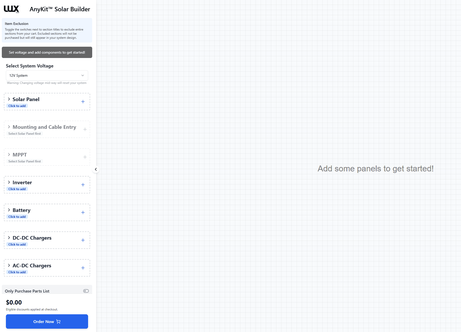
14 steps to design a complete off-grid solar system — from calculating your daily loads to generating a wiring diagram. The same process built into the AnyKit Solar Builder.
Solar Harvest
Panels, mounting, strings, and MPPT controllers
Energy Storage
Batteries, DC-DC chargers, and AC-DC chargers
Distribution & Protection
Wiring, fuses, busbars, inverters, and isolators

Step 1. Calculate Your Daily Energy Needs
Before choosing any hardware, work out how much energy you actually use. List every appliance — fridge, lights, phone chargers, water pump — along with its wattage and daily run-time. Multiply watts by hours to get watt-hours (Wh). Total everything up for your daily load in Wh/day.
- List every DC and AC appliance you plan to run
- Multiply wattage x hours/day for each appliance
- Add 15-20% buffer for inefficiencies and future expansion
- Consider seasonal changes — winter loads are often higher
Step 2. Choose Your System Voltage
System voltage determines the current flowing through your wires and directly affects wire sizing, fuse ratings, and component compatibility. Most campervans and caravans use 12V. Larger systems (boats, off-grid cabins) may benefit from 24V or 48V to reduce current and allow thinner cables over longer runs.
- 12V — most common for campervans, caravans, and small boats
- 24V — mid-size systems, reduces current by half vs 12V
- 48V — large off-grid installations, minimises cable losses
- All components must match your chosen system voltage

Step 3. Size and Select Solar Panels
Your panels need to harvest enough energy each day to cover your loads plus charging losses. Divide your daily load by the average peak sun hours for your location. Factor in real-world losses (~20%) from temperature, shading, and controller efficiency. Then choose panels that fit your roof space and mounting method.
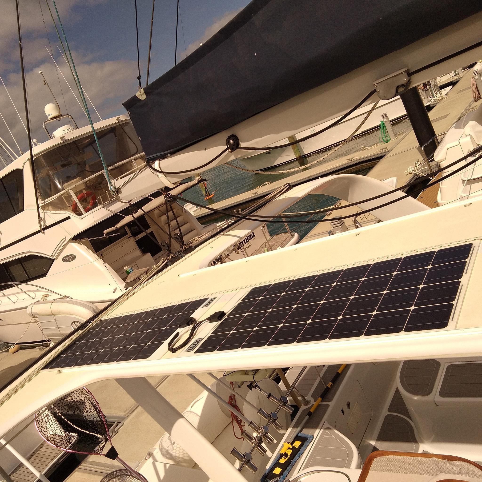
- Monocrystalline panels offer the best efficiency per m²
- Flexible panels suit curved surfaces but have shorter lifespans
- Key specs: Voc (open circuit voltage), Vmp, Imp, Isc, wattage
- Temperature coefficients affect voltage — critical in hot climates

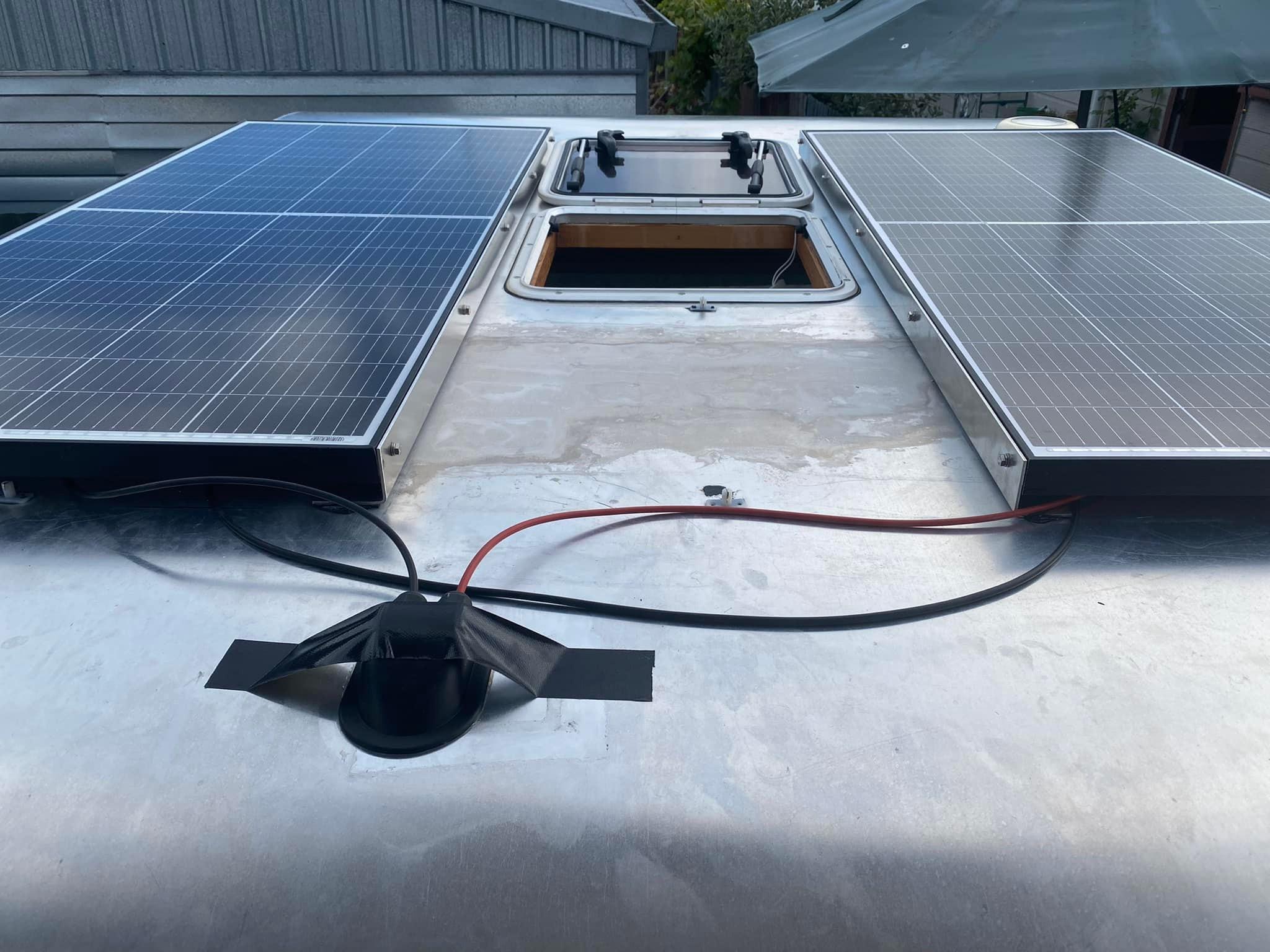
Step 4. Plan Your Panel Mounting and Roof Entry
Mounting hardware secures your panels to the roof and determines tilt angle, ventilation, and long-term durability. Aluminium brackets are the standard for fixed installations. Flexible panels bond directly with adhesive. Every roof-mounted system needs a weatherproof cable entry gland to bring wires inside without leaks.
- Corner or Z-brackets for rigid panels — allow airflow underneath
- Adhesive mounting for flexible panels on curved roofs
- Waterproof cable glands prevent leaks at roof penetrations
- Sealant (Sikaflex or equivalent) around every fixing point
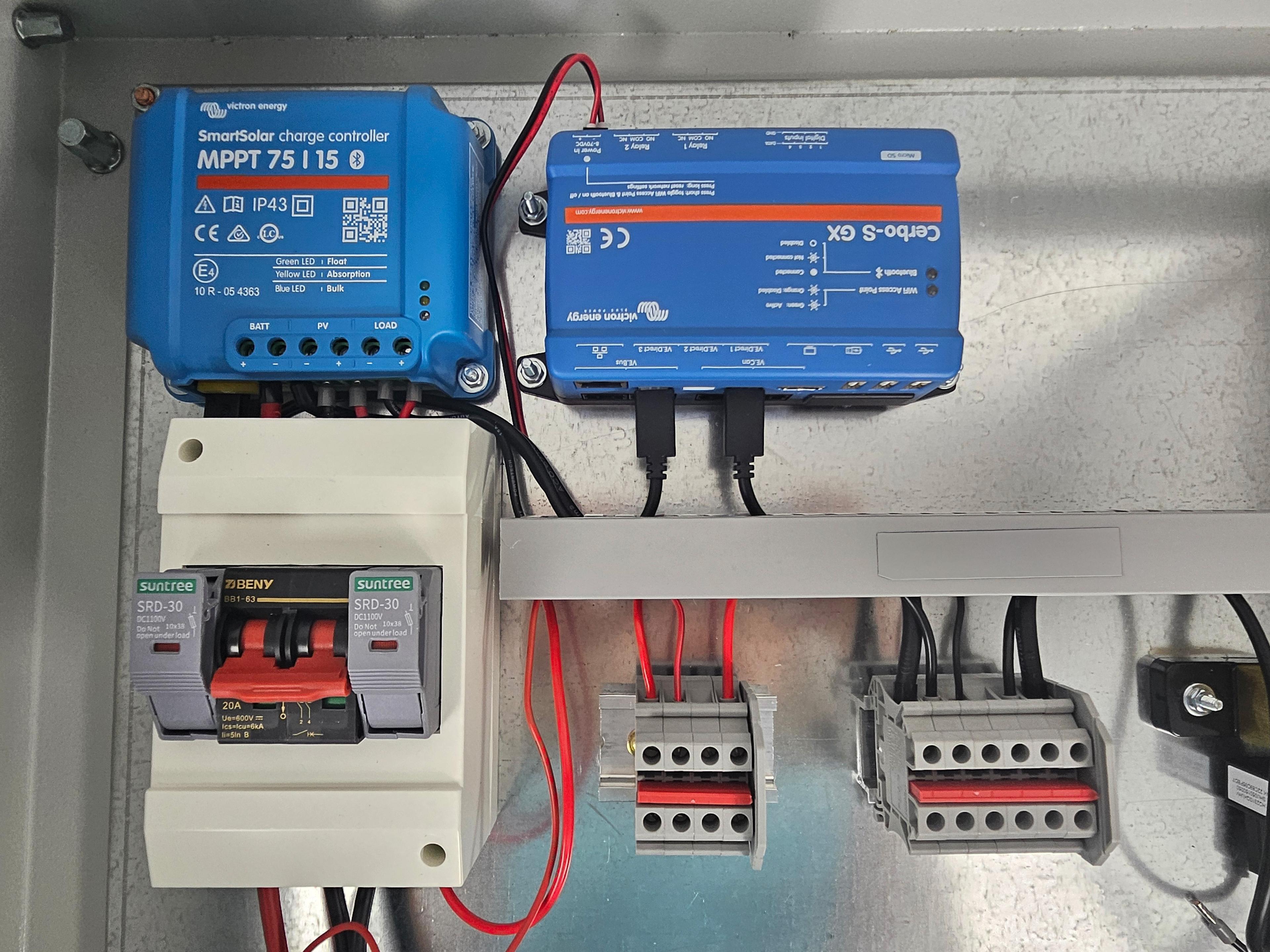
Step 5. Select an MPPT Charge Controller
The MPPT charge controller sits between your panels and battery. It converts the higher panel voltage down to battery voltage while maximising power extraction. Sizing is critical: the controller must handle your array's maximum open-circuit voltage (temperature-adjusted) and total short-circuit current.
- MPPT is 15-30% more efficient than PWM controllers
- Max Voc input must exceed your coldest-temperature Voc
- Battery charge current rating must match your battery specs
- Multi-tracker controllers suit mixed panel orientations

Step 6. Configure Panel Strings
Panels can be wired in series (voltages add), parallel (currents add), or a combination. Series strings must stay within your controller's Voc limit. Parallel strings must stay within the Isc limit. The AnyKit engine automatically evaluates every valid combination and selects the configuration that maximises utilisation.
- Series: increases voltage, same current — fewer parallel cables
- Parallel: increases current, same voltage — needs MC4 Y-connectors
- Never exceed controller max Voc (adjust for coldest expected temp)
- Mismatched panels in series reduces output to the weakest panel

Step 7. Size Your Battery Bank
Your battery bank stores energy for use when the sun isn't shining. LiFePO4 (lithium iron phosphate) batteries are the standard for mobile solar — they're lighter, offer deeper discharge (80-100% DoD), and last 3,000+ cycles. Size your bank to cover at least 1-2 days of autonomy without solar input.
- LiFePO4: 100% usable capacity, 10+ year lifespan
- AGM/Gel: only 50% usable (must not discharge below 50%)
- Check max charge current — don't exceed battery manufacturer limits
- Batteries in parallel increase capacity; in series increase voltage

Step 8. Add DC-DC Charging (Alternator)
A DC-DC charger lets your vehicle's alternator charge the house battery while driving. It regulates voltage and current to match your battery chemistry, and isolates the two battery systems so your starter battery is never drained. Essential for vehicles that drive regularly — it can fully charge your bank during a few hours of driving.
- Isolated DC-DC chargers protect smart alternators
- Non-isolated models share the negative — simpler wiring
- Size based on alternator spare capacity (typically 20-40A)
- Some models include MPPT solar input as a bonus

Step 9. Add AC-DC Charging (Shore Power)
When plugged into mains power at a campground or marina, an AC-DC charger converts 230V AC to the correct DC voltage for your battery bank. Multi-stage charging profiles (bulk, absorption, float) ensure safe, complete charging. Choose a charger rated for your battery chemistry and desired charge speed.
- Match charger output voltage to your battery bank voltage
- LiFePO4 requires a charger with a lithium profile
- Higher amperage = faster charging when on shore power
- Some inverter/chargers combine both functions in one unit
Step 10. Choose an Inverter for AC Loads
An inverter converts your 12/24/48V DC battery power into 230V AC for household appliances — coffee machines, laptops, microwaves. Size it for your peak continuous load plus surge requirements (motors and compressors draw 3-5x their rated power at startup). Pure sine wave inverters are essential for sensitive electronics.
- Pure sine wave — safe for all electronics and appliances
- Modified sine wave — cheaper but can damage sensitive devices
- Continuous rating must exceed your total AC load
- Surge rating must handle motor startup currents
Step 11. Size All Wiring
Every circuit needs the correct wire gauge to carry its current safely without excessive voltage drop. Undersized wires overheat and cause fires; oversized wires waste money. Calculate the required cross-section for each cable run based on current, length, and acceptable voltage drop (typically <3% for DC circuits).
- Voltage drop should be <3% for most DC circuits
- Higher current = thicker cable (or higher system voltage)
- Longer runs need thicker cable to compensate for resistance
- Use tinned marine-grade cable for boats and wet environments
Step 12. Add Overcurrent Protection
Every cable needs a fuse or circuit breaker rated between the expected load current and the cable's ampacity. Fuses protect against short circuits and overloads. Place them as close to the power source as possible. The AnyKit engine automatically selects the correct fuse ratings and holders for each circuit in your system.
- Fuse rating: above load current, below cable ampacity
- Place fuses within 200mm of the battery positive terminal
- Use ANL/MEGA fuses for high-current circuits (battery, inverter)
- Use blade fuses or breakers for branch circuits (lights, USB)
Step 13. Distribution: Busbars, Shunts, and Isolators
Busbars provide a central connection point for multiple positive or negative cables — much cleaner and safer than daisy-chaining terminals. A battery shunt monitors current flow for accurate state-of-charge readings. Isolator switches let you disconnect circuits for maintenance or emergencies.
- Positive busbar with fuse holders — one fused output per circuit
- Negative busbar — common return point for all circuits
- Battery shunt on the negative side for monitoring (e.g. Victron SmartShunt)
- Main battery isolator for emergency disconnect
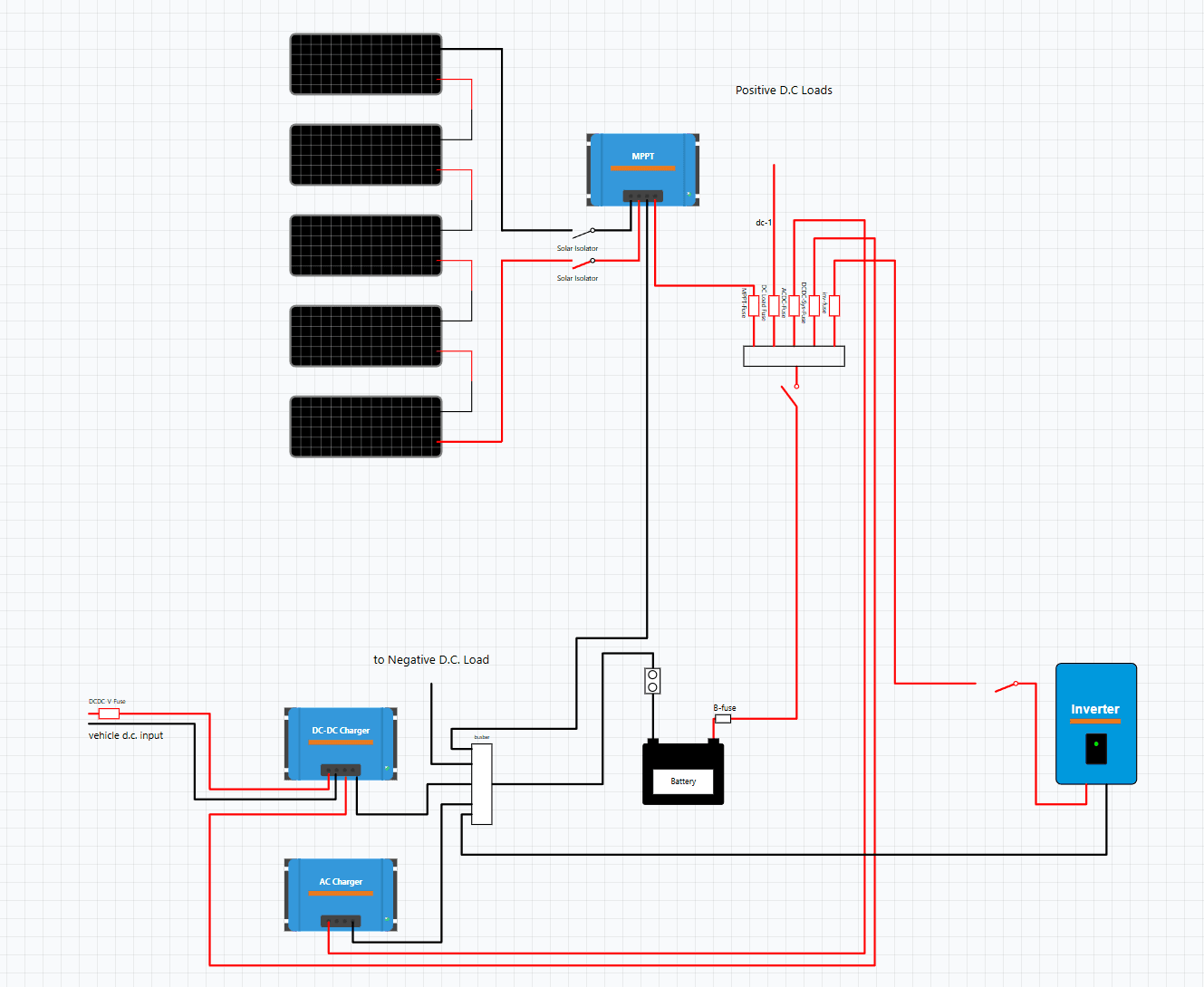
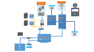
Step 14. Generate Your Wiring Diagram and Parts List
With all components selected, the AnyKit Solar Builder automatically generates a compliant wiring diagram showing every connection, fuse, and cable specification. It also produces a complete, priced parts list so you can order everything you need in one go. No guesswork, no missed components.
- Auto-generated wiring diagram with correct cable colours
- Every fuse, cable lug, and connector included automatically
- Parts list with pricing — order with one click
- Compliant with AS/NZS low-voltage wiring standards

Ready to Design Your System?
The AnyKit Solar Builder walks you through every step above and generates a compliant wiring diagram with a full parts list.